ARTICLE
What Actually Drives the Design of Water and Wastewater Structures
Trend pieces date quickly. The loads, exposure and detailing decisions that actually govern a water or wastewater structure do not — they are the same ones a design has to answer whether the year is this one or the next.
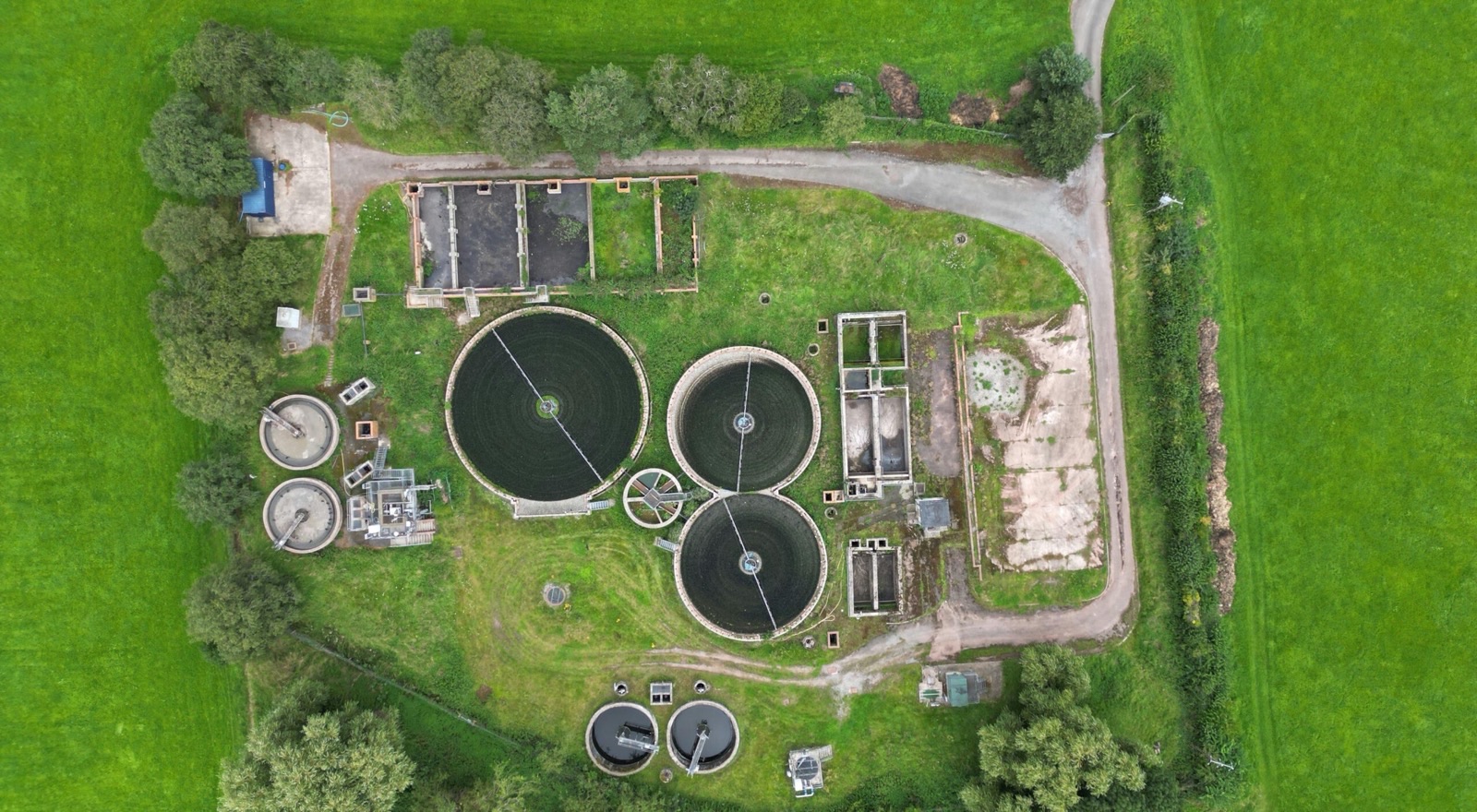
Hydraulic and structural loading unique to water infrastructure
A water or wastewater structure carries loads a typical building never sees. A full tank applies hydrostatic pressure that increases with depth and acts outward on every wall below the water line — the opposite direction from most building loads, which resolve down through columns to a foundation. An empty tank next to a full one, a condition that happens routinely during cleaning or maintenance, can load a shared wall from the other side entirely, which is why differential filling is a load case a liquid-retaining structure has to survive, not an operational inconvenience to design around.
Dynamic loading adds another layer. Pumps, mixers and aeration equipment introduce vibration and cyclic loading that a static analysis does not capture on its own, and surge pressure from a rapid valve closure or a pump trip can spike well above the steady operating pressure a pipeline or a channel wall was sized for. None of these are unusual conditions on a treatment plant — they are the ordinary operating envelope, and the structure has to be designed against all of them, not just the steady-state case that is easiest to calculate.
Containment integrity and crack control
A liquid-retaining wall is designed to a tightness class, which sets an allowable crack width tighter than the strength check on the same section would require. The mechanism matters: concrete cracks under restrained shrinkage and thermal movement long before it is anywhere near its strength limit, and a wall can be more than strong enough to carry its load while still cracking wide enough to weep. Reinforcement in a liquid-retaining structure is therefore detailed to distribute cracking into many fine cracks rather than a few wide ones — closer bar spacing, not necessarily more steel — because fine, well-distributed cracking is largely self-sealing under continuous exposure to water, and a few wide cracks are not.
Construction sequencing feeds directly into this. Pour sizes, curing time between adjacent pours, and the placement of movement or construction joints all affect how much restrained shrinkage a given panel experiences, which means crack control is decided partly on the drawing and partly in the pour sequence the contractor actually follows.
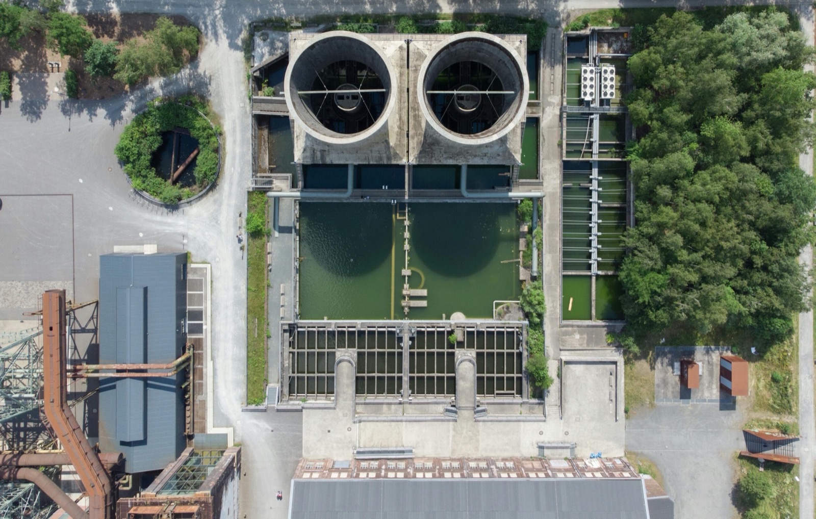
Corrosion and material durability in an aggressive environment
The headspace above certain wastewater treatment stages generates hydrogen sulphide gas, which converts to sulphuric acid on exposed concrete surfaces in the presence of moisture and specific bacteria — a slow mechanism, but one that has visibly degraded concrete crowns in sewers and digesters over a working life measured in decades. Where this exposure is expected, the durability response is specific: increased cover, sulphate-resisting or specially formulated concrete, and in the most aggressive zones a protective lining rather than relying on cover alone.
Chemical dosing areas raise a related but distinct question, since the relevant exposure is whatever chemical is being dosed, not a generic corrosive assumption. Steel elements in these zones need a coating or material specification matched to the actual chemical present, and exposure class has to be set structure by structure across a treatment plant rather than applied uniformly, because a digester, a chemical dosing room and a clean-water tank age at entirely different rates under the same blanket assumption.
Buried structures, groundwater and buoyancy
A structure below the water table has to be designed for external hydrostatic pressure acting inward, in addition to the soil load, and the two do not always act together at their worst case — a design has to check the combinations, not just the individual loads. The condition that catches an unwary design is buoyancy: an empty or partially empty buried tank can weigh less than the groundwater it displaces, and without enough dead load, ballast or a base slab designed specifically against uplift, an emptied tank can float, crack, or shift out of position during routine maintenance rather than during any unusual event.
This load case has to be checked at every stage the structure will actually see — empty for inspection, partially full during commissioning, full in normal operation — because the worst case for buoyancy is frequently not the worst case for strength, and a design that only checks the full, in-service condition can miss it entirely.
Seismic and dynamic behaviour of liquid-retaining structures
A tank responds to ground motion differently from a building, because the liquid inside it responds too. Under seismic loading, the contained liquid separates into two distinct components: an impulsive mass that moves rigidly with the tank wall, and a convective mass, the sloshing component, that moves independently at its own, usually much longer, period. Both have to be captured in the analysis, because designing only for the impulsive mass understates the wall pressure, and ignoring sloshing misses the freeboard a tank needs at the top to avoid overtopping or damaging its roof during an earthquake.
In regions of meaningful seismic hazard this changes wall design, freeboard allowance and the anchorage of any roof or internal fittings, and it is a distinct calculation from the static tightness-class check the same wall also has to pass. A structure can meet its serviceability crack-width limit under normal loading and still need a materially different wall section once the seismic load case governs.
Phased construction and operational continuity
Most treatment plant work is an upgrade or an expansion to a facility that has to keep treating flow throughout construction, since a municipality or an industrial site rarely has the option to simply stop. That constraint shapes the structural design as much as any load case does: new structures are tied into existing ones that were built to an earlier code and may not have been modelled since, temporary bypass and flow-diversion structures need their own structural design even though they are not permanent, and the construction sequence has to guarantee that at every stage enough treatment capacity stays online.
The intermediate conditions during a phased build — a partially demolished tank, a temporary wall carrying a load the final design never intended it to — are frequently where the least load certainty exists, which is why a design for a live treatment plant documents each construction stage in as much structural detail as the finished condition, rather than treating phasing as a construction-sequencing problem separate from the engineering.