ARTICLE
Steel Columns Explained: Types, Design Essentials and BIM Applications
A steel column looks like the simplest member in a frame until its base connection, its splice or its fire protection is detailed. This is what the common column types are for, what governs their design, and what changes when they are modeled rather than drawn.
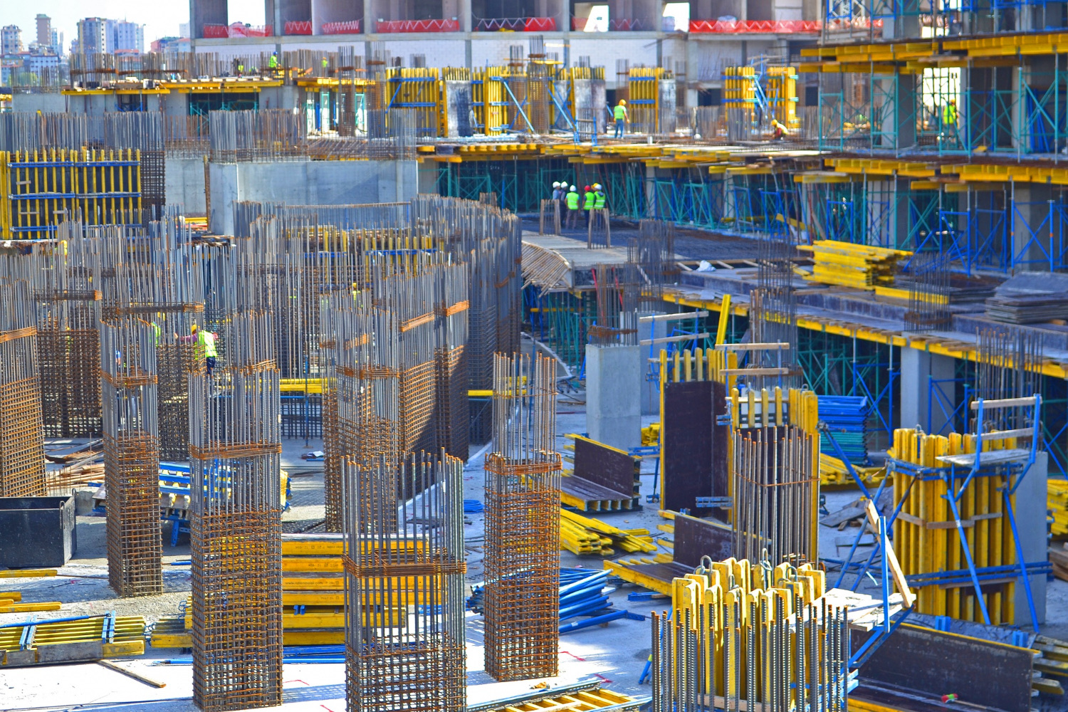
What a steel column actually carries
A steel column's job sounds simple — carry the load above it down to its foundation — and the simplicity is mostly an illusion created by how rarely a real column carries only that load in only that direction. Floor and roof reactions bring axial compression, but frame action, wind and seismic loading bring moment, and a beam that lands eccentrically on a column face brings a moment the column was never drawn to expect unless someone checked for it.
The design problem that actually governs most columns is not crushing the material — steel is very good in pure compression — but buckling: the column deflecting sideways under load before the material itself is overstressed. That behavior is controlled by slenderness, a ratio of the column's unbraced length to its radius of gyration, and by the effective length factor, which accounts for how the column's ends are actually restrained rather than assuming they are perfectly pinned or perfectly fixed. Get the effective length assumption wrong and every other number in the calculation is computed correctly against the wrong problem.
Common column types and where each is used
- Wide-flange (I-section) columns — the most common choice in conventional framing, efficient where bending is dominant about one axis, and straightforward to connect beams to at the flange or web. Most standard steel frames default to this section family unless a specific condition argues otherwise.
- Hollow structural sections (HSS/box columns) — efficient in both axes at once, which suits columns that see significant bending in more than one direction, and often chosen where the column is architecturally exposed and a clean, four-sided profile matters. The trade-off is connections: bolting into a closed section is harder than bolting into an open one, and many HSS connections end up welded or use blind-bolt or through-plate details instead.
- Built-up and plate girder columns — fabricated from plate rather than selected from a rolled catalog, used where the load exceeds what a standard rolled section can carry economically, or where an unusual cross-section shape is needed for architectural or clearance reasons.
- Composite columns — a steel section encased in or filled with concrete, combining steel's strength and ductility with concrete's mass, stiffness and inherent fire resistance. Increasingly common on taller or heavily loaded frames where a pure steel section would need to be uneconomically large.
The right choice is rarely about one column in isolation. It follows from the framing strategy, the connection details the frame relies on elsewhere, and how the column is meant to behave as part of the whole lateral system, not just under its own tributary load.

Base plates and splices: where columns actually fail in detailing
Two locations account for a disproportionate share of steel column detailing problems, and both sit at a discontinuity rather than along the member itself.
The base plate transfers the column's load into the foundation through bearing on concrete or grout, sized so the bearing stress stays within the concrete's capacity, with anchor bolts sized and positioned for whatever tension and shear the base actually has to resist. A pinned-base column needs a comparatively simple plate and a modest anchor pattern. A fixed-base column resisting real moment needs a larger plate, anchor rods positioned further from the neutral axis to develop the necessary lever arm, and often stiffeners to keep the plate from deforming under the moment before the anchors engage. Grout specification and leveling procedure belong on the drawing, not left to site practice, because an unlevelled or under-strength grout bed changes the bearing assumption the whole design relies on.
Column splices, where one length of column is jointed to the next between floors, split into bearing splices — where compression is transferred through direct contact of milled, flush-fitting ends, with the splice plates mainly holding the pieces in alignment — and moment splices, where plates and bolts have to be sized for the actual moment and shear present at that specific level, not copied from a splice detail used elsewhere in the frame. Choosing the splice location to avoid a level with an unusually high moment, where the geometry allows it, is one of the simplest decisions that makes a splice detail dramatically easier to design and to build.
Fire protection and durability
Structural steel loses strength quickly as temperature rises, which is why fire protection is a design decision for a column, not an afterthought applied once the frame is fixed. The required fire-resistance rating — commonly expressed as a period the member must maintain adequate capacity under standard fire exposure — drives the protection method, and the three common approaches trade cost, appearance and coordination differently. Intumescent coatings, a thin film that expands into an insulating char under heat, preserve the visual profile of the steel and suit architecturally exposed columns, at a higher cost per unit of protection than the alternatives. Board or spray-applied fireproofing is generally the most economical option and suits concealed columns where appearance does not matter. Concrete encasement, tying back to the composite column category, adds fire resistance as a consequence of adding structural mass, which can make it the more efficient choice on a frame that was heading toward composite columns anyway.
Whichever method is chosen, its thickness or buildup changes the column's effective profile, which has to be coordinated with the architectural finish and with any clearance the column needs from adjacent elements — a coordination point that is trivial to resolve in a model and easy to miss on drawings produced independently of one.
What changes when a column is modeled, not drawn
A column defined as a parametric family in a model, rather than drawn independently on each sheet it appears on, behaves differently through the life of a project. A change to a base plate detail or a section size, made once at the type level, propagates to every instance of that column that uses it, instead of requiring someone to find and update every sheet where it was previously drawn by hand. Base plate, splice and column schedules generated directly from the model stay in agreement with the drawings by construction, rather than being compiled separately and drifting out of sync the first time someone forgets to update one after updating the other.
Modeling connections explicitly, rather than representing them with a typical detail and a note, is what makes clash detection meaningful at the column: a base plate's real anchor bolt projection, a splice plate's actual bolt clearance, or a fireproofing buildup's real thickness can be checked against a services route or an architectural finish before either is built, not discovered when they meet on site. The same model supports erection sequencing and staged analysis, letting a temporary, partially braced condition during construction be checked against the same geometry the finished structure uses, rather than assumed to be fine because the finished condition is.
Standards that govern column design
Column buckling design differs by code in its detail, even though the underlying physics is the same everywhere. AISC 360 governs compression member design in North America, with buckling strength computed from a column curve based on slenderness and expressed against the member's critical stress. EN 1993-1-1 governs steel columns under the Eurocode system, using a family of buckling curves selected according to the section's shape and axis of buckling, applied with the National Annex of the country of construction. AS 4100 governs the equivalent design in Australia and New Zealand, with its own slenderness-based capacity reduction approach.
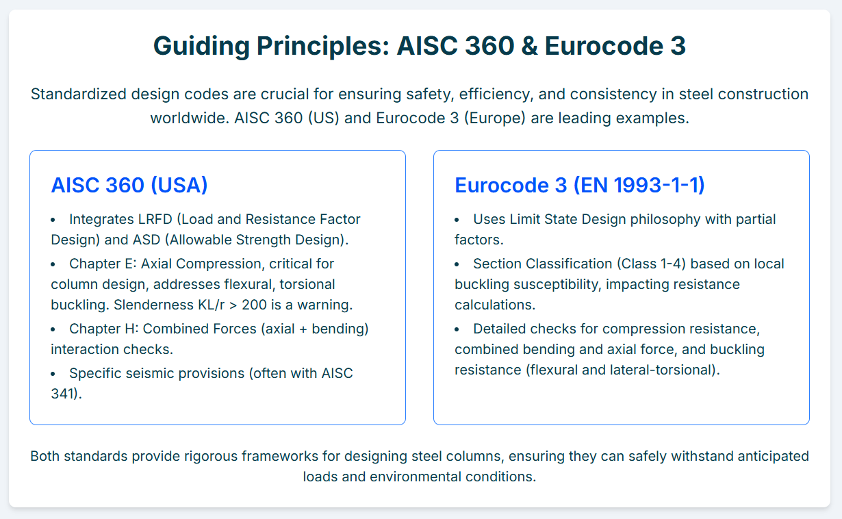
The practical consequence for detailing is that a column designed under one code and re-checked under another will not simply carry across: the effective length factor may be derived differently, the buckling curve selection is not identical, and connection design philosophy — particularly around moment splices and base plate stiffening — varies enough between systems that a package has to commit to one governing standard from the outset rather than blending assumptions from more than one.