ARTICLE
Understanding BIM LOD: Precision and Clarity Across Project Phases
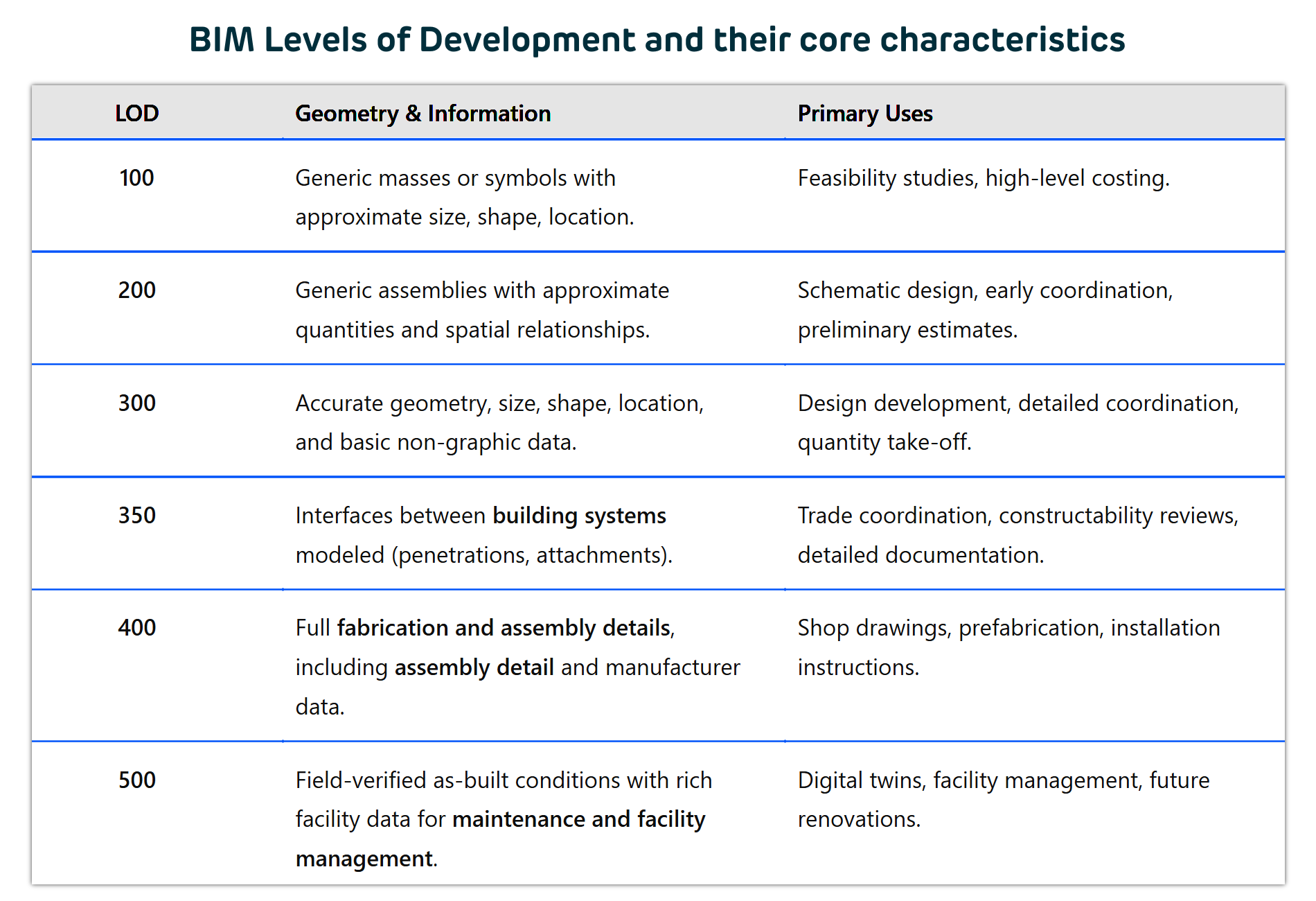
LOD 100 and LOD 300 can look similar on screen and mean completely different things about what you can rely on. Here is what each level from LOD 100 to LOD 500 actually commits a model to, and how to pick the right one for what you are using it for.

What LOD actually defines
Level of Development — LOD — gets used loosely as a stand-in for how detailed a model looks, which is a misleading way to think about it. LOD is a commitment about reliability, not just geometry. Every model element at a given LOD level answers two separate questions: what geometry and information does it actually contain, and how much can a downstream user trust that content for a specific purpose.
That distinction matters because a model can look finished and still be the wrong thing to build from. A wall rendered with full visual detail at LOD 200 might still carry only an approximate thickness and a placeholder material — accurate enough for early coordination, not accurate enough for a fabricator to cut material against. LOD exists so that everyone on a project — architect, engineer, fabricator, owner — reads the same model and understands the same thing about what it can be relied on for at that stage, without having to ask.
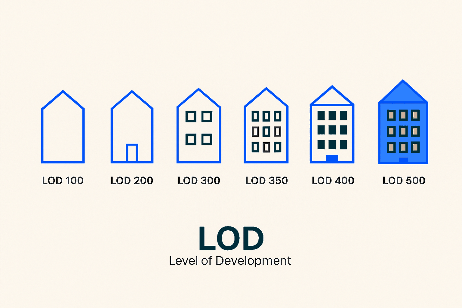
LOD 100 and LOD 200: what the early stages actually commit you to
The two earliest levels get the least explanation in most LOD discussions, which is unfortunate, because using them for the wrong purpose is where a lot of early-project confusion starts.
- LOD 100 is conceptual. An element at this level may not carry explicit geometry at all — a symbol or a generic massing volume is enough, as long as it conveys overall area, height, volume, location and orientation. It supports feasibility studies, early massing options and high-level analysis such as orientation for solar exposure. It does not support taking quantities or dimensions off the model — nothing in it is precise enough yet to measure.
- LOD 200 introduces generic systems and assemblies: approximate size, shape, location and orientation, sometimes with non-graphic information attached. A wall exists as a wall, with a roughly correct thickness; a duct run follows a general path without a fixed size or exact routing. This is enough for early space planning — checking that a ceiling void can plausibly hold the systems it needs to — but the moment someone asks for exact clearances or a quantity for a cost estimate, LOD 200 geometry is being asked to answer a question it was never built to answer.
LOD 300: the stage coordination and construction documents actually depend on
LOD 300 is where geometry stops being approximate. Every element is modeled with accurate size, shape, location and orientation — a specific wall with its actual layers and thickness, a specific structural member with its real profile and position, not a generic stand-in for either.
That precision is what makes the rest of the workflow trustworthy. Clash detection between architectural, structural and MEP systems only means something if the geometry being compared is accurate — a clash flagged between two LOD 200 placeholders tells you very little, while a clash between two LOD 300 elements is a real coordination problem worth resolving. Construction documents and permit sets are drawn from LOD 300 models for the same reason: the drawings need to reflect true design intent, not an approximation of it. Quantity take-offs at this level are reliable enough to support cost estimation, because the volumes and areas being measured are the actual ones, not placeholders.
What LOD 300 still leaves out is the fabrication layer: bolt patterns, weld preparation, hanger assembly detail. That boundary is deliberate — LOD 300 is the coordinated design, not yet the buildable component.
LOD 400: modeled to build from, not just to review
LOD 400 adds exactly what LOD 300 leaves out: the detail a fabricator or installer needs to actually make and assemble the component — connections, bolt holes, weld details, hanger assemblies, and manufacturer-specific part information where it applies. A shop drawing can be generated directly from an LOD 400 element rather than redrawn from a coordination model.
This is the level prefabrication depends on. A panel, module or steel assembly built off-site has to be correct before it ever reaches the site — there is little room to adjust a precast panel or a welded steel assembly once it has left the shop. Modeling to LOD 400 for whatever will be prefabricated, or whatever is structurally complex and exposed, is what makes that off-site approach viable instead of risky.
The practical benefit is fewer surprises in the field — not because the model looks more impressive, but because the ambiguity that normally gets resolved on site, whether something actually fits, whether a connection actually works, has already been resolved on paper before fabrication started.
LOD 500: the model as a record of what was actually built
LOD 500 changes what the model is for. Instead of representing design intent, it represents field-verified, as-built conditions — geometry updated to match what a site survey or laser scan actually found, alongside the metadata a facility manager needs to operate the building: serial numbers, warranty terms, operations and maintenance documentation, service intervals.
LOD 300 and LOD 400 exist to get a building built correctly. LOD 500 exists so the people running it afterward are not relying on a design drawing that may or may not describe what is actually behind the wall. It gives facility teams a model they can use to locate components, plan maintenance and manage assets through the building's operational life — and because its accuracy is verified against the real, constructed building rather than assumed from design documents, it is the natural starting point for a digital twin.
Matching LOD to the decision it needs to support
The common mistake runs in both directions. Modeling everything to LOD 400 by default is slow and expensive when most of a project never needs fabrication-level detail. Using LOD 200 geometry to produce a cost estimate or a tender submission invites disputes later, because that geometry was never accurate enough to be relied on that way in the first place.
The practical approach is to set the required LOD per element, per project phase, tied to the decision that element needs to support at that point: massing at LOD 100 for a feasibility study, coordination at LOD 300 once systems need to fit together without clashing, fabrication detail at LOD 400 for whatever will be prefabricated or is too complex to leave to site adjustment, and LOD 500 once the building exists and someone has to run it. Written down as a requirement rather than assumed, that mapping is what keeps a model useful at every stage, instead of either underbuilt or over-engineered for what it is actually being asked to do.